Call us: +48 58 6228900
 Feedback
 Newsletter


How switches work and how to match their contacts to the load?
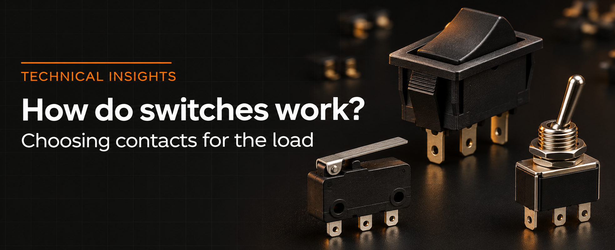
A mechanical switch changes electrical connections by moving contacts. Although the function is simple, correct selection requires more than checking the number of terminals and the current printed on the housing. The same component may work correctly with a resistive load but cause problems with a motor, a power supply with large input capacitance or a microcontroller input. Reliability depends on conditions during making, carrying and breaking current.
What happens inside a switch
Force applied to a button, lever or slider moves the mechanism and changes the position of a moving contact relative to fixed contacts. In snap-action basic switches, an elastic mechanism transfers the contacts after a defined operating point is reached. Contact movement can then be much faster than the movement of the actuator pressing the switch. Snap action does not, however, eliminate contact bounce or contact-surface wear.
A momentary switch returns to its rest position when actuation force is removed. A maintained switch retains the selected state. A panel pushbutton is therefore not necessarily momentary, and a rocker switch does not necessarily have only maintained positions. Determine the operating function from the specifications of the particular model.
Reading contact configurations
A pole is an independent circuit operated mechanically together with any other poles. The number of throws identifies the available switched connections for each pole. SPST, SPDT, DPST and DPDT describe contact topology, but do not by themselves specify maintained operation, load ratings or switching sequence.
|
Type |
Function |
Typical contact terminal count |
|
SPST |
One circuit opened or closed |
2 |
|
SPDT |
One pole switched between two outputs |
3 |
|
DPST |
Two circuits opened or closed together |
4 |
|
DPDT |
Two poles switched together between output pairs |
6 |
NO means normally open and NC means normally closed. For a momentary switch, the normal state is the state without force applied to the actuator. In a typical changeover arrangement, COM is the common terminal connected to either NC or NO. Do not infer terminal positions solely from the appearance of the housing.
Break-before-make versions disconnect the previous path before establishing the new one. Make-before-break versions connect both paths briefly. This distinction matters when selecting a signal source, for example. The SPDT designation alone does not establish which switching sequence a product provides.
Why an AC rating cannot be applied directly to DC
When a load is disconnected, an electrical arc can form between separating contacts. In an AC circuit, periodic current zero crossings help extinguish the arc. DC has no such natural zero crossing, so the arc may persist longer. Breaking capability also depends on voltage, contact separation and mechanism design.
A rating of 5 A at 250 VAC does not imply approval to break 5 A at 250 VDC. Ratings should not be converted on the basis of constant power V · I either. Permitted combinations of voltage, current and load type must come from the documentation or manufacturer confirmation.
Operating current does not describe the complete load
When switching on a motor, incandescent lamp or power supply input, current can greatly exceed its steady-state value. For a capacitive load, charging energy and current limitation by source and wiring impedance are important. For example, with a 12 V supply and an assumed total resistance of 1.5 Ω, the initial current charging a discharged capacitance is approximately 8 A.
I0 ≈ V / R = 12 V / 1.5 Ω = 8 A
This is a simplified example. The actual pulse also depends on inductance, ESR, current limiting and source behaviour. It nevertheless shows why a device drawing 0.3 A during normal operation may require a switch capable of handling a much higher making current.
Breaking a coil or another inductive load produces a voltage associated with falling current. Suppression must suit both the load and the required response. A diode across a DC coil, for example, limits the transient but may increase the electromagnet’s release time. No single protection circuit is suitable for every switch and load.
Why a power switch is not always suitable for signals
For a logic input, the minimum applicable load matters as well as the maximum current. Surface films and contamination can impair conduction at very low currents. Such applications require contact versions intended for low-level signals, often with a suitable gold finish. Suitability is determined by the specifications of the particular version.
If a pushbutton connects an input to ground while a 10 kΩ resistor pulls it up to 3.3 V, the pressed-state current is approximately 0.33 mA. Compare this voltage and current combination with the manufacturer’s specified conditions. A 3 A marking on the switch does not establish reliability in that circuit.
Contact bounce and multiple counts from one press
After touching, contact surfaces can separate and reconnect several times before settling. Similar behaviour can occur when a button is released. A user perceives a single press, but a fast digital input may detect a series of edges. Contact bounce can therefore produce multiple counts or unintended state changes.
Software debouncing can accept a new state only after it has remained unchanged for a defined interval. In an illustrative algorithm, the input is sampled every 1 ms and a change is accepted after 12 ms without a sampled transition. Any further transition restarts the timer. The 12 ms interval is a design assumption that must be matched to the switch and permitted latency.
An RC filter and a hysteresis input
Short pulses can be filtered in hardware using a resistor, capacitor and Schmitt-trigger input. The time constant τ = R · C defines the charging rate in a particular path, but is not automatically the debounce time. The logic transition also depends on input thresholds, component tolerances and the capacitor discharge path.
For R = 22 kΩ and C = 220 nF, the time constant is 4.84 ms. If the capacitor charges from 0 V towards 3.3 V through that resistor, it reaches 70% of the supply after approximately 5.83 ms. This calculation uses an assumed threshold, not a guaranteed response time for an arbitrary input.
V(t) = VS · [1 − exp(−t/τ)]
A hysteresis input has different thresholds for rising and falling signals, helping prevent repeated transitions on a slow edge. The capacitor discharge pulse through the contacts must also be limited where required by the circuit design. A capacitor connected to an ordinary digital input is not a universal solution.
Operating force and actuator travel
For a basic switch, check operating position OP, release position RP and permitted overtravel OT. The difference between operating and release positions represents mechanical hysteresis. This matters in position detection because contact state depends on both the current position and the direction of movement.
The equipment mechanism must ensure reliable operation despite assembly tolerances without overloading the plunger or lever. Greater force does not automatically improve contact quality and can damage the housing, mechanism or PCB. In lever versions, the force application point affects the required force and displacement.
Mechanical life and electrical life
Mechanical life describes mechanism operation under the manufacturer’s specified test conditions, usually without switching an electrical load. Electrical life refers to operation with a specified load. One million mechanical operations does not mean one million interruptions at maximum current. Load type, operating frequency and temperature must be considered.
Selecting a switch for equipment
Tactile switches are often used in user interfaces, DIP switches for configuration settings and snap-action basic switches for position detection. Rocker, slide and panel switches are selected according to circuit function and loading. Maritex offers a range of switch constructions, so begin selection with the required contact function, voltage, actual current waveform and mounting method.